PDF Publication Title:
Text from PDF Page: 011
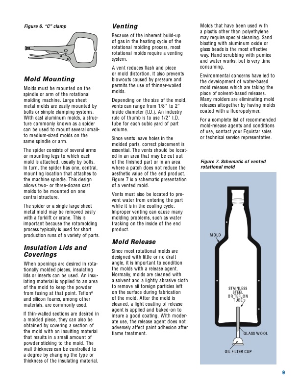
Figure 6. “C” clamp Mold Mounting Molds must be mounted on the spindle or arm of the rotational molding machine. Large sheet metal molds are easily mounted by bolts or simple clamping systems. With cast aluminum molds, a struc- ture commonly known as a spider can be used to mount several small- to medium-sized molds on the same spindle or arm. The spider consists of several arms or mounting legs to which each mold is attached, usually by bolts. In turn, the spider has one, central, mounting location that attaches to the machine spindle. This design allows two- or three-dozen cast molds to be mounted on one central structure. The spider or a single large sheet metal mold may be removed easily with a forklift or crane. This is important because the rotomolding process typically is used for short production runs of a variety of parts. Insulation Lids and Coverings When openings are desired in rota- tionally molded pieces, insulating lids or inserts can be used. An insu- lating material is applied to an area of the mold to keep the powder from fusing at that point. Teflon® and silicon foams, among other materials, are commonly used. If thin-walled sections are desired in a molded piece, they can also be obtained by covering a section of the mold with an insulting material that results in a small amount of powder sticking to the mold. The wall thickness can be controlled to a degree by changing the type or thickness of the insulating material. Venting Because of the inherent build-up of gas in the heating cycle of the rotational molding process, most rotational molds require a venting system. A vent reduces flash and piece or mold distortion. It also prevents blowouts caused by pressure and permits the use of thinner-walled molds. Depending on the size of the mold, vents can range from 1/8" to 2" inside diameter (I.D.). An industry rule of thumb is to use 1/2" I.D. tube for each cubic yard of part volume. Since vents leave holes in the molded parts, correct placement is essential. The vents should be locat- ed in an area that may be cut out of the finished part or in an area where a patch does not reduce the aesthetic value of the end product. Figure 7 is a schematic presentation of a vented mold. Vents must also be located to pre- vent water from entering the part while it is in the cooling cycle. Improper venting can cause many molding problems, such as water tracking on the inside of the end product. Mold Release Since most rotational molds are designed with little or no draft angle, it is important to condition the molds with a release agent. Normally, molds are cleaned with a solvent and a lightly abrasive cloth to remove all foreign particles left on the surface during fabrication of the mold. After the mold is cleaned, a light coating of release agent is applied and baked-on to insure a good coating. With moder- ate use, the release agent does not adversely affect paint adhesion after flame treatment. Molds that have been used with a plastic other than polyethylene may require special cleaning. Sand blasting with aluminum oxide or glass beads is the most effective way. Hand scrubbing with pumice and water works, but is very time consuming. Environmental concerns have led to the development of water-based mold releases which are taking the place of solvent-based releases. Many molders are eliminating mold releases altogether by having molds coated with a fluoropolymer. For a complete list of recommended mold-release agents and conditions of use, contact your Equistar sales or technical service representative. Figure 7. Schematic of vented rotational mold MOLD STAINLESS STEEL OR TEFLON TUBE GLASS WOOL OIL FILTER CUP 9PDF Image | A Guide to Rotational Molding Equistar
PDF Search Title:
A Guide to Rotational Molding EquistarOriginal File Name Searched:
Guide_Rotational_Molding.pdfDIY PDF Search: Google It | Yahoo | Bing
Development of a solar powered Electric Ship The Electricship website originally started off as a project to develop a comprehensive renewable, affordable, modular electric ship... More Info
Modular Boat Hull Composite The case for a unsinkable, modular composite hybrid boat hull... More Info
MS Burgenstock Hybrid Electric Catamaran Lake Lucerne Unique shuttle servicing Lucerne to the Burgenstock Resort... More Info
Ground Power Unit GPU Powered by Lithium Ion Batteries The goal of the Ground Power Unit is to provide a readily accessible, modular, ready-to-power solution for remote power... More Info
| CONTACT TEL: 608-238-6001 Email: greg@electricship.com | RSS | AMP |