PDF Publication Title:
Text from PDF Page: 010
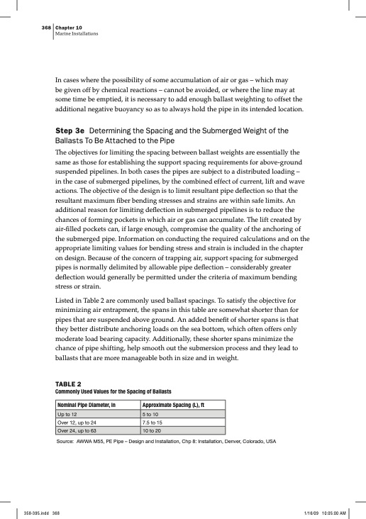
368 Chapter 10 Marine Installations In cases where the possibility of some accumulation of air or gas – which may be given off by chemical reactions – cannot be avoided, or where the line may at some time be emptied, it is necessary to add enough ballast weighting to offset the additional negative buoyancy so as to always hold the pipe in its intended location. Step 3e Determining the Spacing and the Submerged Weight of the Ballasts To Be Attached to the Pipe The objectives for limiting the spacing between ballast weights are essentially the same as those for establishing the support spacing requirements for above-ground suspended pipelines. In both cases the pipes are subject to a distributed loading – in the case of submerged pipelines, by the combined effect of current, lift and wave actions. The objective of the design is to limit resultant pipe deflection so that the resultant maximum fiber bending stresses and strains are within safe limits. An additional reason for limiting deflection in submerged pipelines is to reduce the chances of forming pockets in which air or gas can accumulate. The lift created by air-filled pockets can, if large enough, compromise the quality of the anchoring of the submerged pipe. Information on conducting the required calculations and on the appropriate limiting values for bending stress and strain is included in the chapter on design. Because of the concern of trapping air, support spacing for submerged pipes is normally delimited by allowable pipe deflection – considerably greater deflection would generally be permitted under the criteria of maximum bending stress or strain. Listed in Table 2 are commonly used ballast spacings. To satisfy the objective for minimizing air entrapment, the spans in this table are somewhat shorter than for pipes that are suspended above ground. An added benefit of shorter spans is that they better distribute anchoring loads on the sea bottom, which often offers only moderate load bearing capacity. Additionally, these shorter spans minimize the chance of pipe shifting, help smooth out the submersion process and they lead to ballasts that are more manageable both in size and in weight. TABLE 2 Commonly Used Values for the Spacing of Ballasts Nominal Pipe Diameter, in Approximate Spacing (L), ft Over 12, up to 24 7.5 to 15 Source: AWWA M55, PE Pipe – Design and Installation, Chp 8: Installation, Denver, Colorado, USA Up to 12 5 to 10 Over 24, up to 63 10 to 20PDF Image | Marine Installations PE
PDF Search Title:
Marine Installations PEOriginal File Name Searched:
PE-Marine-Installations.pdfDIY PDF Search: Google It | Yahoo | Bing
Development of a solar powered Electric Ship The Electricship website originally started off as a project to develop a comprehensive renewable, affordable, modular electric ship... More Info
Modular Boat Hull Composite The case for a unsinkable, modular composite hybrid boat hull... More Info
MS Burgenstock Hybrid Electric Catamaran Lake Lucerne Unique shuttle servicing Lucerne to the Burgenstock Resort... More Info
Ground Power Unit GPU Powered by Lithium Ion Batteries The goal of the Ground Power Unit is to provide a readily accessible, modular, ready-to-power solution for remote power... More Info
| CONTACT TEL: 608-238-6001 Email: greg@electricship.com | RSS | AMP |