PDF Publication Title:
Text from PDF Page: 007
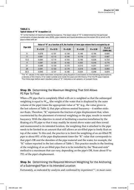
TABLE 1 Typical values of “K” in equation 3.0 “K” is the fraction of maximum potential buoyancy. The exact value of “K” is determined by the particular combination of pipe diameter ratio (SDR), pipe material and liquid densities and the extent (R) to which a PE pipe is filled with air* Chapter 10 365 Marine Installations Value of “K” as a function of R, the fraction of inner pipe volume that is occupied by air Pipe SDR 9 -0.078 -0.107 -0.136 13.5 -0.084 -0.119 -0.155 21 -0.089 -0.130 -0.170 32.5 -0.093 -0.137 -0.180 -0.166 -0.195 -0.190 -0.226 -0.210 -0.251 -0.224 -0.268 -0.604 -0.723 -0.817 -0.879 R = 0.10 R = 0.15 R = 0.20 R = 0.25 R = 0.30 R =1.0 (100% Air) 11 -0.081 -0.113 -0.146 -0.178 -0.211 -0.667 17 -0.087 -0.125 -0.163 -0.202 -0.240 -0.776 26 -0.091 -0.133 -0.176 -0.218 -0.260 -0.850 * The “K” values in this table have been computed using Equation 2 and based on the following assumptions: a density of 62.3 lbs/cu ft for water outside and inside the pipe and 59.6 lbs/cu ft for the PE pipe material. The minus sign before each resultant value of “K” indicates a net upward, or buoyant force. Step 3b Determining the Maximum Weighting That Still Allows PE Pipe To Float When a PE pipe that is completely filled with air is weighted so that the submerged weighting is equal to WDW (the weight of the water that is displaced by the outer volume of the pipe) times the appropriate value of “K” (e.g., the value given in the last column of Table 1), that pipe achieves neutral buoyancy – it neither sinks nor floats. Therefore, “K” represents the fraction of pipe displacement that, when counteracted by the placement of external weighting on the pipe, results in neutral buoyancy. With the objective in mind of facilitating a marine installation by the floating of a PE pipe so that it may readily be stored above water and then towed and maneuvered to its intended location, the weighting that is attached to the pipe needs to be limited to an amount that still allows an air-filled pipe to freely float on top of the water. To this end, the practice is to limit the weighting of an air-filled PE pipe to about 85% of the pipe displacement times the “K” value that corresponds to that pipe’s DR and the densities of the pipe material and the water, for example, the “K” values reported in the last column of Table 1. This practice results in the limiting of the weighting of an air-filled pipe that is to be installed by the “float-and-sink” method to a maximum that can vary, depending on the pipe’s DR, from about 57 to 75% of the pipe’s displacement. Step 3c Determining the Required Minimum Weighting for the Anchoring of a Submerged Pipe in its Intended Location Fortunately, as indicated by analysis and confirmed by experience(1,2), in most casesPDF Image | Marine Installations PE
PDF Search Title:
Marine Installations PEOriginal File Name Searched:
PE-Marine-Installations.pdfDIY PDF Search: Google It | Yahoo | Bing
Development of a solar powered Electric Ship The Electricship website originally started off as a project to develop a comprehensive renewable, affordable, modular electric ship... More Info
Modular Boat Hull Composite The case for a unsinkable, modular composite hybrid boat hull... More Info
MS Burgenstock Hybrid Electric Catamaran Lake Lucerne Unique shuttle servicing Lucerne to the Burgenstock Resort... More Info
Ground Power Unit GPU Powered by Lithium Ion Batteries The goal of the Ground Power Unit is to provide a readily accessible, modular, ready-to-power solution for remote power... More Info
| CONTACT TEL: 608-238-6001 Email: greg@electricship.com | RSS | AMP |